|
Disc Spring DIN 2093
100 INR/Piece
Product Details:
X
Disc Spring DIN 2093 Price And Quantity
- 1 Piece
- 100 INR/Piece
Disc Spring DIN 2093 Trade Information
- 100 Piece Per Day
- 1 Days
Product Description
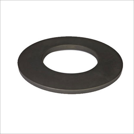
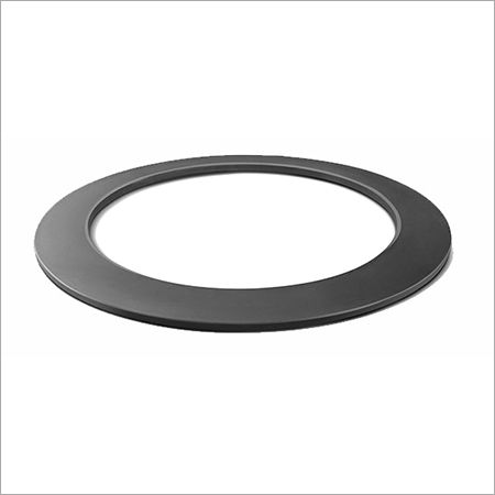
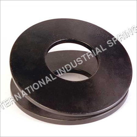
Disc Spring DIN 2093
Disc springs are generally formed in angular concial shapes. Equipped onto the axial position, these components come with a remarkable sequence of high pressure within a small space, which has a custom-built deviance combination.
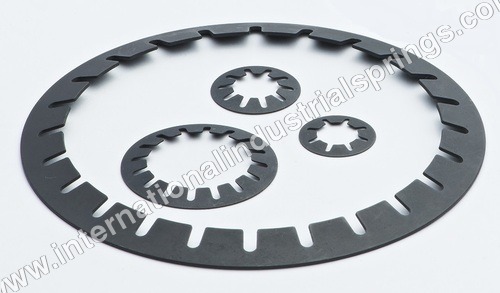
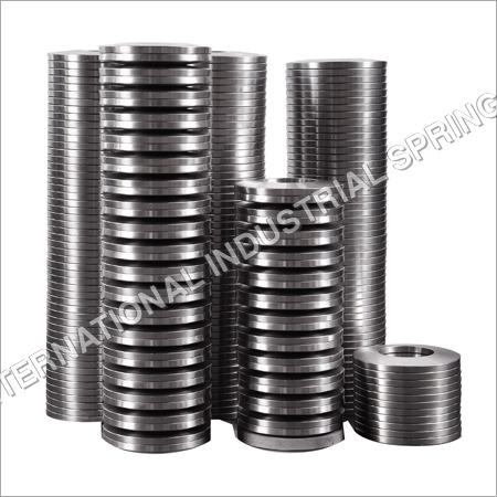
These products offered by us at IIS, provide a fantastic array of solutions thanks to their technological built. Used in a majority of the engineering companies, they can be utilized as a single disc or multiple, in the form of heaps. Such stacks can consist of springs which are in the form of a series set or parallel set. One can acquire these with or without contact flats, depending on your choice. Fabricated in compliance to the DIN 2092, our team of proficient experts customize each and every item, so as to equip each patron with a performance-packed commodity. The group 1 & 2 Disc Springs are Austempered, which is a process of treating the high fatigue products via high degrees of heat.
Stacked in parallel
Absolute deflection=Deflection of 1 disc
Full Weight= Load on 1 disc X no.of discs.
In Series
Full deflection= Deflection of 1 disc X no. of discs in stack
Overall weight = Load on 1 disc
Parallel Series combinations
It can be strategically created to suit just about any pressure or deflection and to attain advanced attributes
Advantages of Disc Springs:
1.Zero impairment or slowing down under normal pressure.
2.Advanced force holding ability.
3.Exceptional durability aspect.
4.Stock keeping is reduced while single spring sizes can be joined universally.
5.Area saving.
6.Being mostly Self-damping in nature, gives the device a phenomenal shock absorption and power scattering attributes.
7.Cost-efficient utilization of space and extreme spring force with small divergence.
8.Flexible to stacking in numerous assemblings.
9.Collection use as a standard spring constituent.
10.Decreased upkeep cost & higher security
11.Reduced height/thickness ratio engaged cuts down stresses
Surface Technology & Coating Services
Being an extremely well reputed organization, International Industrial Springs is also rendering a trusted and reliable array of finishing services on all components fabricated. List of coverings are available below.
DISC SPRING APPLICATION
* Automotive & Engines
* Brakes & Clutches
* Dampers
* Hoists
* Machine Tools
* Shock Mounts
* Vibrators
Selection
a) In case the application concerns massive numerics of deflection rounds, (the process is known as dynamic application) or if the necessary units have a crucial value, the we highly urge our patrons to select through a DIN 2093 adhering range of Disc Springs.
b) Thanks to our vast product line up, one can acquire the precise item which would work in perfect harmony with your devices. Aiding in lowering the machine pressure, it would enhance the service life of your equipments to a phenomenal degree. In case a wider diversion occurs through the stacked columns, then the diameter springs would guarantee the most brief achievable stack length.
c) When we talk about Static or dynamic utilizations, make sure you choose a Disc Spring which, at 75% of its total available deflection, provides the maximum force and bend needed.
d) One the production process in completed, there is a certain degree of residual tensile pressures which are felt. The upper internal side of the diameter boundary helps to return this into a normal compressive force at a time when the Disc is deflected upto a level of 15 per cent of it’s complete capability.
DISC SPRING INSTALLATION, SETTING & STACKING
Installation:
a) Major applications which include quantifiable array of deviation cycles need an additional toughened seating faces. The guide faces on the other hand need to be equally tough so as to minimize the immoderate wear of stepping. Speaking of both the support washers and guide elements, the surface needs to be finely polished, and their should be a hardness of around 58HRC while keeping the depth at 0.60mm min.
b) A vital requirement which would help in multiplying the durability aspect of these items, is an advanced lubricant. In the case of low-duty, Disc Spring application, one requires a solid lubricant, such as the molybdenum-disulphide, grease, which is to be applied on the connection points and placement surfaces of the spring.
Disc Spring with Contract Flats and Reduced Thickness: For Disc
When one creates springs which have a specific thickness of more than 6mm, the DIN 2093 rules specifies the manufacturer to apply miniature contact surfaces at point I III, along with rounded corners. This enhances the point of load application, while decreasing the rubbing at the guide road point. The contact flat accelerates spring pressure, which is thus compensated via a decrement in the thickness from ‘t’ to ‘T’.
Stacking :
Series Stacking: The additional effect of the bearing point which is caused due to the constant rubbing of the springs stacked in a series, would enable the components at the end to deflect much more than that in the center. In exceptional cases, this may lead to over-compaction and premature failure of the end springs. The “rule of thumb” point which is applied, generally means that the dimension of the stacked sprinds should never go over a length of approximately 3 times the external diameter of the Disc Spring.
Stack Length :
In the case of Disc Spring stacking, a constant attempt should be made so as to keep the stacks as brief-length as possible. The friction, merged with other influence cause the stack to be more uneven while deviating more on the side of loading. Generally, such an effect is ignored for a ‘normal stack’, but this is not the same in the case of long stacks. In such a situation, the pile is stabilized, which is mostly done by dividing the same with guide washers.
DISC SPRING : SYMBOLS & UNITS
Symbols and Units : Standard sizes acquirable as per DIN 2093
Group Classification of Disc springs
Tolerances:
Costs is quite and important factor for everyone. The springs which are acquired by each patron should be affordable. Tolerances in particular should be benevolent enough so as to allow the manufacturing of certified springs by simple development methods. We always suggest tolerances only as per the functional specifications and details of a business. This aids the spring maker to make modifications, thus enabling them to compensate for the given constants existing in the size and mechanical characteristics of all spring components.
Another advice which we offer to product designers, is that if the modular drawing forms come with modern day endurance containers with specific dimensions, then they are definitely impractical for springs. One should remove the same and rather install down-to-earth tolerances which meet the necessary tolerances of the compulsory spring specifcs.
The rules and regulations followed by us at International Industrial Springs are in strict adherence to the standards laid down by the DIN 2093. In general, our team of experts carry out their work professionally, while designing each temperament in varied sizes, which can vary as per the customized specifications laid down by our patrons.This also applies to our ball-bearing Disc Springs.
Theoretical vs Measured Characteristic of a Disc Spring
One of the most crucial attributes of our Disc Spring lineup is that they are non-linear. The shape of the devices strictly count on the ho/t ratio. In the lower segment of the diversion range, the practical characteristic is slightly different from the theoretical. In a case where S/ho>0.75, then the the practice region again distances on an increasing line from the theoretical, only because the instruments roll upon each other, or on a bearing surface which in turn causes the lever arm to shorten continuously. This is precisely why the pressure of the spring is kept at Ss=0.75 ho as per DIN 2093.
DISC SPRING APPLICATION
- Automotive & Engines
- Brakes & Clutches
- Dampers
- Hoists
- Machine Tools
- Shock Mounts
- Vibrators
| Group | Thickness of single disc in mm | Single disc with Ground ends & reduced material |
|---|---|---|
| 1 | less than 1.25 | No |
| 2 | From 1.25 to 6 | No |
| 3 | Over 6 upto 14 | Yes |
Symbols and Units
| Symbol | Unit | Term |
|---|---|---|
| De | mm | Outside diameter |
| Do | mm | Inside diameter |
| E | mm | Mean diameter |
| F | N/mm2 | Modulus of elasticity |
| ho | N | Formed height |
| lo | mm | Free overall height of spring in its initial position |
| s | mm | Deflection of single disc |
| t | mm | Thickness of single disc |
| t1 | mm | Reduced thickness of single disc in the case of springs with ground ends (group 3) |
| µ | mm | Poisson's ratio |
| d OM,ol,oil, | N/mm2 | Design stresses at the points designated OM, I, II, III, and IV |
| ▲F | N | Relaxation |
DISC SPRINGS : Std Din 2093 ( IIS Disc Springs )
| SERIES A | ||||||
|---|---|---|---|---|---|---|
| De | Di | t | H0 | lo | S | F |
| 8.0 | 4.2 | 0.4 | 0.2 | 0.60 | 0.15 | 210 |
| 10 | 5.2 | 0.5 | 0.25 | 0.75 | 0.19 | 329 |
| 12.5 | 6.2 | 0.7 | 0.3 | 1.00 | 0.23 | 673 |
| 16 | 8.2 | 0.8 | 0.3 | 1.10 | 0.23 | 813 |
| 18 | 9.2 | 1.0 | 0.4 | 1.4 | 0.30 | 1250 |
| 20 | 10.2 | 1.1 | 0.45 | 1.55 | 0.34 | 1530 |
| 22.5 | 11.2 | 1.25 | 0.5 | 1.75 | 0.38 | 1950 |
| 25 | 12.2 | 1.5 | 0.55 | 2.05 | 0.41 | 2910 |
| 31.5 | 16.3 | 1.75 | 0.7 | 2.45 | 0.53 | 3900 |
| 35.5 | 18.3 | 2.0 | 0.8 | 2.80 | 0.60 | 5190 |
| 40 | 20.4 | 2.25 | 0.9 | 3.15 | 0.68 | 6540 |
| 45 | 22.4 | 2.5 | 1.0 | 3.50 | 0.75 | 7720 |
| 50 | 25.4 | 3.0 | 1.1 | 4.10 | 0.83 | 12000 |
| 56 | 28.5 | 3.0 | 1.3 | 4.30 | 0.98 | 11400 |
| 63 | 31 | 3.5 | 1.4 | 4.90 | 1.05 | 15000 |
| 71 | 36 | 4.0 | 1.6 | 5.60 | 1.20 | 20500 |
| 80 | 41 | 5.0 | 1.7 | 6.70 | 1.28 | 33700 |
| 90 | 46 | 5.0 | 2.0 | 7.00 | 1.50 | 31400 |
| 100 | 51 | 6.0 | 2.2 | 8.20 | 1.65 | 48000 |
| 112 | 57 | 6.0 | 2.5 | 8.50 | 1.88 | 43800 |
| 125 | 64 | 8.0 | 2.6 | 10.60 | 1.95 | 85900 |
| 140 | 72 | 8.0 | 3.2 | 11.20 | 2.40 | 85300 |
| 160 | 82 | 10 | 3.5 | 13.50 | 2.63 | 139000 |
| 180 | 92 | 10 | 4.0 | 14.00 | 3.00 | 125000 |
| 200 | 102 | 12 | 4.2 | 16.2 | 3.15 | 183000 |
| 225 | 112 | 12 | 5.0 | 17 | 3.75 | 171000 |
| 250 | 127 | 14 | 5.6 | 19.6 | 4.20 | 249000 |
| SERIES B | ||||||
|---|---|---|---|---|---|---|
| De | Di | t | H0 | lo | S | F |
| 8.0 | 4.2 | 0.3 | 0.25 | 0.55 | 0.19 | 119 |
| 10 | 5.2 | 0.4 | 0.3 | 0.7 | 0.23 | 213 |
| 12.5 | 6.2 | 0.5 | 0.35 | 0.85 | 0.26 | 291 |
| 14 | 7.2 | 0.5 | 0.40 | 0.9 | 0.30 | 279 |
| 16 | 8.2 | 0.6 | 0.45 | 1.05 | 0.34 | 412 |
| 18 | 9.2 | 0.6 | 0.5 | 1.2 | 0.38 | 572 |
| 20 | 10.2 | 0.7 | 0.55 | 1.35 | 0.41 | 745 |
| 22.5 | 11.2 | 0.8 | 0.65 | 1.45 | 0.49 | 710 |
| 25 | 12.2 | 0.8 | 0.7 | 1.6 | 0.53 | 868 |
| 28 | 14.2 | 0.9 | 0.8 | 1.8 | 0.60 | 1110 |
| 31.5 | 16.3 | 1.0 | 0.9 | 2.15 | 0.68 | 1920 |
| 35.5 | 18.3 | 1.25 | 1.0 | 2.25 | 0.75 | 1700 |
| 40 | 20.4 | 1.25 | 1.15 | 2.65 | 0.86 | 2620 |
| 45 | 22.4 | 1.5 | 1.3 | 3.05 | 0.98 | 3660 |
| 50 | 25.4 | 1.75 | 1.4 | 3.4 | 1.05 | 4760 |
| 56 | 28.5 | 2.0 | 1.6 | 3.6 | 1.20 | 4440 |
| 63 | 31 | 2.0 | 1.75 | 4.25 | 1.31 | 7180 |
| 71 | 36 | 2.5 | 2.0 | 4.5 | 1.50 | 6730 |
| 80 | 41 | 2.5 | 2.3 | 5.3 | 1.73 | 10500 |
| 90 | 46 | 3.0 | 2.5 | 6.0 | 1.88 | 14200 |
| 100 | 51 | 3.5 | 2.8 | 6.3 | 2.10 | 13100 |
| 112 | 57 | 3.5 | 3.2 | 7.2 | 2.40 | 17800 |
| 125 | 64 | 4.0 | 3.5 | 8.5 | 2.63 | 30000 |
| 140 | 72 | 5.0 | 4.0 | 9.0 | 3.00 | 27900 |
| 160 | 82 | 6.0 | 4.5 | 10.5 | 3.38 | 41100 |
| 180 | 92 | 6.0 | 5.1 | 11.1 | 3.83 | 37500 |
| 200 | 102 | 8.0 | 5.6 | 13.6 | 4.20 | 76400 |
| 225 | 112 | 8.0 | 6.5 | 14.5 | 4.88 | 70800 |
| 250 | 127 | 10 | 7.0 | 17 | 5.25 | 119000 |
| SERIES c | ||||||
|---|---|---|---|---|---|---|
| De | Di | t | H0 | lo | S | F |
| 8.0 | 4.2 | 0.2 | 0.25 | 0.45 | 0.19 | 39 |
| 10 | 5.2 | 0.25 | 0.3 | 0.55 | 0.23 | 58 |
| 12.5 | 6.2 | 0.35 | 0.45 | 0.8 | 0.34 | 152 |
| 14 | 7.2 | 0.35 | 0.45 | 0.8 | 0.34 | 123 |
| 16 | 8.2 | 0.35 | 0.4 | 0.9 | 0.38 | 155 |
| 18 | 9.2 | 0.4 | 0.45 | 1.05 | 0.45 | 214 |
| 20 | 10.2 | 0.50 | 0.65 | 1.15 | 0.49 | 254 |
| 22.5 | 11.2 | 0.60 | 0.80 | 1.40 | 0.60 | 425 |
| 25 | 12.2 | 0.70 | 0.90 | 1.60 | 0.68 | 601 |
| 28 | 14.2 | 0.80 | 1.00 | 1.80 | 0.75 | 801 |
| 31.5 | 16.3 | 0.80 | 1.05 | 1.85 | 0.75 | 687 |
| 35.5 | 18.3 | 0.90 | 1.15 | 2.05 | 0.86 | 831 |
| 40 | 20.4 | 1.00 | 1.30 | 2.30 | 0.98 | 1020 |
| 45 | 22.4 | 1.25 | 1.60 | 2.85 | 1.20 | 1890 |
| 50 | 25.4 | 1.25 | 1.60 | 2.85 | 1.20 | 1550 |
| 56 | 28.5 | 1.50 | 1.95 | 3.45 | 1.45 | 2620 |
| 63 | 31 | 1.80 | 2.35 | 4.15 | 1.76 | 4240 |
| 71 | 36 | 1.80 | 2.60 | 4.60 | 1.95 | 5140 |
| 80 | 41 | 2.25 | 2.95 | 5.20 | 2.21 | 6610 |
| 90 | 46 | 2.5 | 3.20 | 5.70 | 2.40 | 7680 |
| 100 | 51 | 2.70 | 3.50 | 6.20 | 2.63 | 8610 |
| 112 | 57 | 3.00 | 3.50 | 6.90 | 2.93 | 10500 |
| 125 | 64 | 3.50 | 3.90 | 8.00 | 3.38 | 15400 |
| 140 | 72 | 3.80 | 4.90 | 8.70 | 3.68 | 17200 |
| 160 | 82 | 4.30 | 5.60 | 9.90 | 4.20 | 21800 |
| 180 | 92 | 4.80 | 6.20 | 11.00 | 4.65 | 26400 |
| 200 | 102 | 5.50 | 7.00 | 12.50 | 5.25 | 36100 |
| 225 | 112 | 6.50 | 7.10 | 13.60 | 5.33 | 44600 |
| 250 | 127 | 7.00 | 7.80 | 14.80 | 5.85 | 50500 |
Thickness Tolerances
| Group | t or t' (mm) | Tolerance for t (mm) |
|---|---|---|
| 1 | 0.2 to 0.6 | +0.02/-0.06 |
| 2 | 1.25 to 3.8 | +0.04/-0.12 |
| 3 | >6.0 to 14.0 | +0.10/-0.10 |
Thickness Tolerances
| Group | t | Tolerance for t (mm) |
|---|---|---|
| 1 | <1.25 | +0.25.0 - 7.5 |
| 2 | 1.25 to 3.0 >3.0 to 6.0 | +0.15 - 7.5 |
| 3 | >6.0 to 14.0 | + 5.0 |
To ensure the specified spring forces, DIN 2093 allows the overall height tolerance to be slightly exceeded.
Other Products in 'Disc Spring Washer' category
Address
INTERNATIONAL INDUSTRIAL SPRINGS
GST : 27AAAFI0815P1ZA
GST : 27AAAFI0815P1ZA
- Plot No. A-26, Road No. 10, Wagle Industrial Estate, Thane - 400604, Maharashtra, India
- Send Inquiry
|
|
|
 |
INTERNATIONAL INDUSTRIAL SPRINGS
All Rights Reserved.(Terms of Use) Developed and Managed by Infocom Network Private Limited. |
